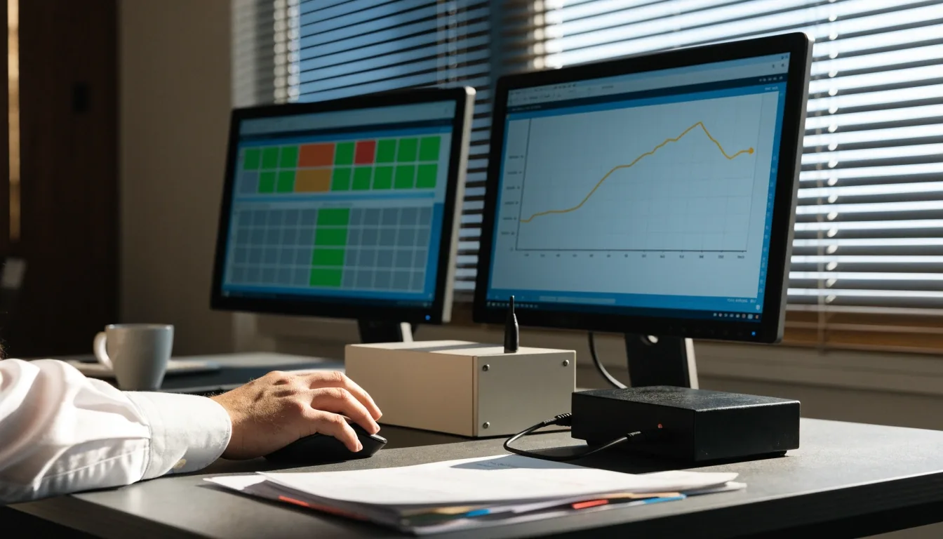
We put your field alarms where you can act on them.
Omniflex RTUs and annunciators are documented for SCADA use, named alongside PLC and DCS in the manuals. Omnix Agent maps your field points, alarms and status into the host your operators already read, so one screen tells the truth about the site.
Serial layer
Field protocol
Host side
Cutover
RS232 / 422 / 485
Modbus RTU
SCADA · PLC · DCS
Parallel, then retire
Integration scope
Where a field point, an alarm and a register map meet your operators’ screen.
Will Omniflex hardware report cleanly into your SCADA?
The honest answer has two halves. What Omniflex RTUs and alarm annunciator panels publish is documented — Modbus RTU, serial ASCII, gateway paths — and it is presented to the host in the names your staff already use. What is not automatic is the last hundred metres between the cabinet and the SCADA database: register maps that mean something, scaling an analog that a field instrument actually produced, alarm polarity that matches the way your operators expect a state to sit at rest, and comm-loss that is visible rather than silent.
Omnix Agent works the second half. We take Teleterm I/O, annunciator states and gateway data and present them to your host, then leave a printed map in the cabinet so the next person who opens the door understands what they are looking at. If your plant already runs Omniflex telemetry, or you have inherited a mixed fleet, the path below is the one we walk.
What integration covers
The five things that turn a cabinet into a trustworthy data source.
What integration covers
We take Teleterm I/O, annunciator states and gateway data and present them to your SCADA host with stable addresses. That includes register maps, scaling for analogs, alarm polarity and comm-loss indication. The host database is updated with plain tag names your staff recognize, so an operator calling a trend line at 3 a.m. reads a name they know.
Register map
Stable addresses for each field point, published on paper and in the host database
Analog scaling
Raw counts or mA converted to the engineering unit the instrument actually reports
Alarm polarity
Steady state told apart from alarm state the way the current panel already behaves
Comm-loss
A watched bit so a dropped link never shows up as a still, unsuspecting value
Tag naming
Host tags written in the names the plant's engineers recognize on the floor
A printed map stays in the cabinet next to the serial bank, so a field engineer with a multimeter can trace a point without opening the SCADA project.
Modbus RTU and serial realities
The port was isolated by design. The plant around it usually was not.
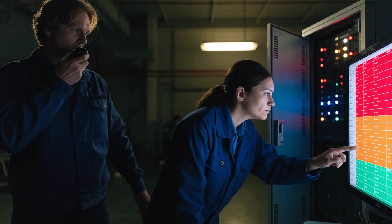
Omniflex documentation describes a fully isolated RS232/422/485 serial port, and RS232 remains common in older control rooms. Before anything is changed, we audit baud rate, parity, addressing and cable shielding. Runs that pass are kept; runs that fail on continuity, isolation or noise are re-routed or replaced. Then polling is tested under load, not with one device quietly online.
Serial interface
RS232 / RS422 / RS485
Fully isolated, as documented for the Omni30 serial stack.
Host protocol
Modbus RTU
A protocol most US plants and utilities already speak.
Pre-cutover test
Full polling load
Tested with every device online, not one of them.
Local control, supervisory view
PLC and DCS alongside SCADA
Most sites keep PLCs for local control and SCADA for supervision — the two layers do different jobs on purpose. Omniflex frames its set around remote monitoring and event management working across those layers, and Omnix Agent maps Omniflex telemetry into whichever side needs the state. Where local PLC logic can stay untouched, it stays untouched. Only the states the SCADA host needs are mirrored upward.
Interposing relays separate voltages and ownership boundaries, so a fault on one side is not carried across to the other. Either side can then be serviced, restarted or swapped without stopping its neighbour.
Where interface work lands
Local PLC logic
Left in place
Supervisory signals
Mirrored up
Boundary between systems
Interposing relay
Ownership on record
Documented
Mixed fleets and gateways
One path for a fleet that was not bought together
When you inherit older monitors — iCAM among them, listed by Omniflex among the supported monitors on the RPN1 page — a gateway that combines their data into one access path cuts host configuration work rather than duplicating it. We record the protocol per device and consolidate only where it is practical to do so. The supported-monitor list guides what can share a path. New devices are added to the same structure, so next year's addition does not mean a second project.
Per-device protocol record
Teleterm RTU on Modbus RTU
Own path
Alarm annunciator panel states
Mapped
iCAM and older monitors
Via gateway
Unsupported monitor stays on its own panel
Not merged
Cutover
The night the old path stops being the one you trust.
Cutover without losing alarms
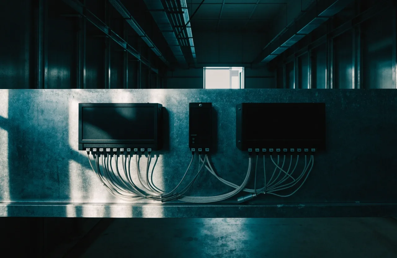
Every point is proven end to end before it is trusted — from the field contact, through the RTU or the alarm annunciator panel, all the way to the SCADA display.
Alarm, return-to-normal and comm-fail states are all shown to the operators watching the screen. Then, during cutover, the old path and the new one run in parallel until their counts match.
Only then is the old path retired. No blind minutes, no window where a signal has no reader behind it.
Parallel path, verified counts, then retire
The cutover is scheduled around the plant's own quiet hours. The old path retires only after the new one has produced matching counts on the alarm summary for the length of a full shift.
Documentation
Documentation you can maintain
Integration lives or dies on paperwork. We deliver I/O lists, register maps, network addresses and backup configurations. File names include site, cabinet and date — not a date code, not an internal reference, but the words the next engineer will actually search for.
Your engineer can add a point next year without reverse-engineering the panel. We review the packet with your team before closeout and walk through how to read it, so the document set survives the people who wrote it.
Closeout packet
I/O list
Every point named, numbered and matched to its field contact
Register map
Modbus addresses with their scaling and their units
Network addresses
Serial port settings, device addresses and their physical runs
Backup configuration
Saved configurations for every device on the path

Support
We stay on the call after closeout
The integration is the beginning of the service, not the end of it. If a register drifts, if a point is added next quarter, if an operator questions what a tag means at 2 a.m., we pick it up. Reach us Monday to Friday, 9:00 AM to 6:00 PM, at the Edina office — the same people who commissioned the cabinet.
Direct lines
Office
4820 W 77th St, Edina, MN 55435
Phone
Hours
Monday to Friday, 9:00 AM – 6:00 PM
Questions
Wiring and ownership, answered plainly.
Questions engineers ask us first
Can legacy serial wiring be reused?
In many cases yes. We test RS232, RS422 and RS485 runs for continuity, isolation and noise, then reuse whatever passes. Replacement is limited to the segments that actually failed. Test results are recorded alongside the rest of the closeout packet, so the decision is on paper rather than in someone's memory of the site visit.
Do you replace our PLC or SCADA?
No. We interface Omniflex hardware to what you already run. Local control stays where it is, supervisory data moves up to the host, and the boundaries between the two are documented. Your existing PLC and SCADA configuration remain the systems of record on either side of the interface.
What does an integration review look like?
We start with the cabinet: what is wired, how it is wired, and what the host is already doing with whatever data it sees. From there we walk the register map, the analog scaling and the alarm polarity against your host's expectations, then agree the cutover window. Most reviews end with a written scope, not a proposal for new hardware.
Can we add points after the site is live?
Yes. New devices are added to the same structure that the packet documents, so a future addition is an edit rather than a second project. Where a gateway is already consolidating older monitors, a new point usually lands on the existing path instead of demanding its own.
Where this goes next
Walk the panel with the people who build the map
Bring the cabinet photo and the tag list if you have them. We will read the register map back the way your operators will see it, point at the places where scaling and polarity usually catch sites out, and tell you plainly what an integration review would cover for your plant.